Zener Diodes Explained: Controlled Breakdown as a Practical Design Tool
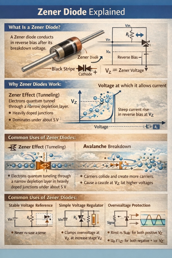
A Zener diode is a semiconductor diode intentionally designed to operate in reverse bias at a predictable voltage. When the reverse voltage reaches a specified threshold—its Zener voltage (VZ)—the diode enters breakdown and conducts strongly, while the voltage across it stays approximately constant over a useful current range. This “nearly constant voltage” behavior makes Zener diodes a foundational building block for simple voltage references, shunt regulators, and voltage clamps.
What makes a Zener diode different from a normal diode?
A standard diode is typically used in forward bias (conducting direction). In reverse bias, it blocks current except for a tiny leakage—until the reverse voltage becomes high enough to cause breakdown. In many diodes, breakdown is not something you want to rely on.
A Zener diode, by contrast, is manufactured so that breakdown happens cleanly and repeatably at a chosen voltage. In that breakdown region, its electrical behavior becomes useful: current can vary substantially while the voltage remains comparatively stable.
Why it works: two breakdown mechanisms
Reverse breakdown in a p–n junction occurs primarily by two physical mechanisms:
- Zener (tunneling) breakdown: In heavily doped junctions the depletion region is very thin, allowing electrons to “tunnel” through the barrier at relatively low voltages.
- Avalanche breakdown: In more lightly doped junctions the depletion region is wider. Carriers accelerated by the electric field collide with the lattice and generate additional carriers (impact ionization), causing a chain reaction at higher voltages.
In practice, many datasheets and engineers say “Zener breakdown” as a general label even when the dominant mechanism is avalanche—because the circuit behavior (a steep I–V curve in reverse breakdown) is what matters for most applications.
Where Zener diodes are used (and why)
1) Voltage reference
The most common role is as a reference voltage in analog and mixed-signal circuits: bias points, thresholds, and simple reference rails. The Zener is operated in breakdown so it holds approximately VZ, and the rest of the circuit uses that as a known reference.
2) Shunt voltage regulation (simple regulator)
A Zener diode can form a shunt regulator: a series resistor feeds a node, and the Zener clamps that node near VZ. It is simple and inexpensive, and can be adequate for small loads and non-critical accuracy. The trade-off is efficiency: current may still flow through the Zener even when the load is light, dissipating power.
3) Overvoltage clamping and protection
Because it conducts heavily above VZ, a Zener can clamp sensitive nodes (for example, protecting an input from exceeding a safe voltage). For high-energy transients, dedicated TVS diodes are often preferred, but Zeners are still used for light-to-moderate clamping where energy is limited and cost/space matter.
How it developed, and the first application
The breakdown effect is named after physicist Clarence Zener, who published a theoretical description of electrical breakdown behavior in solids in 1934.
As semiconductor manufacturing matured (notably silicon junction diodes), engineers realized that controlled reverse breakdown could be exploited in circuits. The earliest standardized and most influential practical use was as a voltage reference element in power-supply regulation—a compact solid-state way to establish a relatively stable voltage. That remains the canonical “first major application class” because it directly leverages the defining property: stable voltage in breakdown.
A simple Zener shunt regulator (schematic + sizing the series resistor)
Below is the classic shunt regulator topology:
           Vin
            +
            |
           RS
            |
   Vout o---+----- Load (Iload) -----> GND
            |
           |<|  Zener diode (reverse-biased)
            |
           GND
What RS does
The Zener diode does not limit its own current. RS is mandatory: it drops the extra voltage and limits current so the Zener stays within its power rating.
Design inputs you need
- Vin_min, Vin_max (minimum/maximum supply voltage)
- VZ (desired Zener voltage)
- Iload_min, Iload_max (load current range)
- IZ_min (minimum Zener current to stay in regulation; often called “knee” current in practice)
- IZ_max (maximum safe Zener current, typically from power rating: IZ_max ≈ PZ_max / VZ)
Step 1: Choose RS to guarantee regulation at worst case (low Vin, high load)
To keep the Zener in breakdown, ensure at least IZ_min flows when supply is lowest and load is highest:RS≤Iload_max+IZ_minVin_min−VZ
(If Vin_min≤VZ, the circuit cannot regulate—there is no headroom.)
Step 2: Check the opposite worst case (high Vin, low load) for Zener overcurrent
Compute Zener current at maximum input and minimum load:IZ=RSVin_max−VZ−Iload_min
Verify IZ≤IZ_max. If it is too high, increase RS (and then re-check Step 1).
Step 3: Power checks (often the part that gets missed)
- Zener dissipation at worst case:
PZ≈VZ⋅IZ_max(actual)
- Resistor dissipation at worst case:
PR≈RS(Vin_max−VZ)2
Select components with adequate margin.
Practical notes (so expectations are realistic)
Zener shunt regulation is simple, but it is not a precision regulator:
- Zener voltage has tolerance and temperature drift
- Breakdown can introduce noise
- Efficiency can be poor at light load (current still burns in the Zener)
For higher performance, designers often use dedicated voltage references or regulator ICs, but the Zener remains valuable for low-cost clamping and simple references.